The Access Virus is a very flexible analogue modeling synthesizer. Besides its oscillators, the two filters contribute to its premium audio qualities.
General
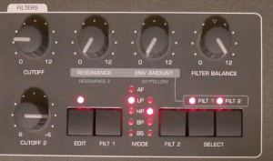
The two filters can be used in two serial modes, a parallel mode, and a split mode. Filter 1 can be used in both 12 and 24 dB modes. It also provides filter saturation or analogue modeling types.
A depiction of the filter modes (Serial 4, Serial 6, Parallel, Split) can be found here.
Since its early incarnations, the Virus provides an (in)famous parameter called »Filter Balance«. At a first glance it is difficult to understand what it does exactly, depending on the abovementioned modes. The manual only sheds little light on what it does exactly. I hope the following description helps to unveil its potential.
Filter Balance in Split Mode
- Oscillator 1 (plus the sub oscillator) feeds Filter 1 which is connected to the left audio output.
- Oscillator 2 (plus 3) feeds Filter 2 which is connected to the right audio output.
- Filter Balance controls the balance between the two filters (respectively outputs).
- In case you want to hear either signal on both speakers, set Pan Spread to 0% in the program edit menu.
Filter Balance in Parallel Mode
- The output of the Mixer section feeds the inputs of either filter.
- Filter Balance acts as a mixer of the two filter signals (Filter 1 only, both, Filter 2 only).
Filter Balance in Serial modes
- At the leftmost position of the Filter Balance knob, the Oscillators as routed through Filter 1 are audible only.
- At the rightmost position of the Filter Balance knob, the Oscillators as routed through Filter 2 are audible only.
- At the center position of the Filter Balance knob, the Oscillators are routed through Filter 1 and then through Filter 2. In case Filter 1 is set to a lowpass filter with a low cutoff setting and Filter 2 is set to a highpass filter with a relatively high cutoff setting, chances are given that almost no signal is remaining at the output of Filter 2.
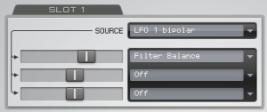
It took me a while to understand the latter behaviour, since I thought in terms of simple analogue circuits respectively the routing of the filters as found in the Korg Z1. The actual behaviour of the Balance knob is more complex than just being a simple balance control. The way it is implemented provides a very musical approach, though. Even more when taking into account that the parameter is controllable via the modulation matrix, e.g. using an LFO.